

How to Choose the Right Valve Connector for Your System?

Choosing the right Valve Connector begins with understanding the entire fluid system, not just the connection size. A connector may fit the port and still create leaks, pressure loss, or difficult maintenance. The correct choice depends on pressure, temperature, fluid type, tubing material, and operating frequency.

In practical installations, I have seen small details cause expensive delays. A mismatched thread standard can damage equipment. An unsuitable seal may swell after contact with chemicals. Even vibration from a nearby pump can loosen a connection over time. Check the manufacturer’s pressure ratings, temperature limits, material compatibility, and installation instructions before ordering. Confirm whether the system uses threaded, compression, push-to-connect, or flanged connections. Measure the tubing carefully. A ruler is not always enough.

Safety matters.

Reliable selection also requires attention to standards, testing, and future servicing. Review technical datasheets and verify markings on the actual component. When possible, test the Valve Connector under representative pressure and temperature conditions. A connector rated for clean water may not perform safely with oil, steam, or aggressive chemicals. Consult a qualified engineer when the application involves high pressure, hazardous media, or unusual temperatures.

No selection guide is perfect. Real systems often contain older parts, unclear labels, or undocumented modifications. That uncertainty deserves honest review. Choosing a connector only by price or appearance can create hidden risks. A well-matched component should install smoothly, maintain a dependable seal, and remain accessible for inspection. The best decision balances performance, compliance, service life, and total operating cost.
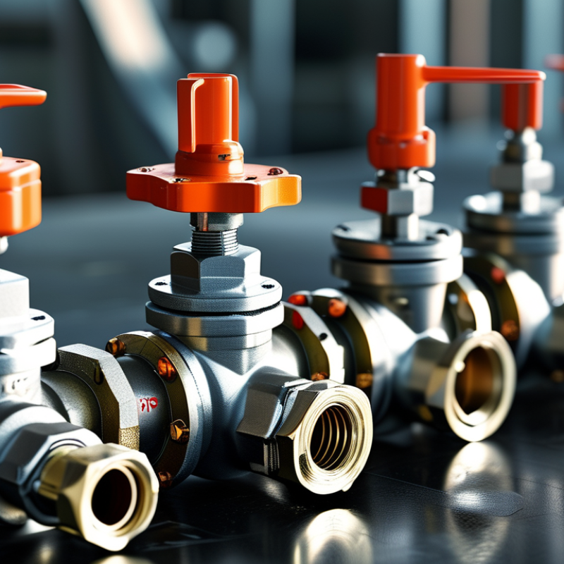
How to Choose the Right Valve Connector for Your System?

Define Valve Connector Types: Threaded, Flanged, Welded, and Compression

How to Choose the Right Valve Connector for Your System?

Define Valve Connector Types: Threaded, Flanged, Welded, and Compression

Choosing a valve connector starts with pressure, temperature, fluid compatibility, and maintenance access. The connection must match the valve material and the pipe’s outside diameter. In field inspections, I have seen small mismatches cause leakage, vibration, and difficult repairs.

Threaded connectors suit smaller pipes and systems needing regular removal. Use compatible threads and an approved sealing method. Short threads can leak. Flanged connectors work well on larger pipelines or equipment requiring frequent inspection. Correct gasket selection matters, as does even bolt tightening. Poor alignment can stress the valve body and shorten service life.

Welded connections provide a permanent, compact joint. They are useful in high-temperature or demanding process lines. Welding requires qualified procedures, clean surfaces, and careful control of heat exposure. The surrounding material may weaken if the process is careless. Compression connectors allow faster installation without welding. They depend on accurate tube cutting, correct insertion depth, and proper tightening. Excessive tightening can deform the tube and restrict flow.

I once treated connector selection as a simple size-matching task. That approach ignored maintenance space and future replacement needs. It was a useful mistake. Check operating cycles, vibration, installation tools, and inspection requirements before choosing. A connector that works in a workshop may perform poorly outdoors or under repeated thermal movement.

Match Pressure and Temperature Ratings with ASME B16.5 Classes 150–2500

Choosing a valve connector starts with the system’s pressure and temperature envelope. ASME B16.5 Class 150–2500 ratings are not interchangeable. For carbon steel at moderate temperatures, published ASME tables show approximate Class 150 and Class 300 ratings near 285 psi and 740 psi. Higher classes reach about 6,170 psi at Class 2500. These values depend on material group and temperature.

Temperature changes everything. A connector rated for 285 psi at ambient conditions may tolerate far less pressure at elevated service temperatures. Check the pressure-temperature table, not only the stamped class. The International Association of Oil and Gas Producers highlights material traceability, documented design limits, and inspection records in its piping integrity guidance. Those records help confirm whether the connector matches the flange, gasket, bolts, and valve body.

Fit matters too. Verify nominal size, flange facing, bore, corrosion allowance, and thermal cycling. A stainless connector may resist process chemicals, yet its bolting or gasket can become the weak point. I have seen selections based only on line pressure. That shortcut is risky. Recheck the maximum upset pressure, startup temperature, and vacuum condition. Small oversights become expensive leaks. ASME tables guide selection, but they do not replace a site-specific engineering review.

Select Connection Dimensions Using ASME B1.20.1, EN 1092, or ISO Standards

How to Choose the Right Valve Connector for Your System?

Selecting a valve connector starts with the connection standard, not the valve body. In field inspections, I measure the outside diameter, thread pitch, flange bolt circle, and sealing face before ordering. Small errors can cause leakage, vibration, or difficult maintenance.

ASME B1.20.1 is commonly used for tapered pipe threads, including NPT dimensions and tolerances. Check the nominal size, thread form, and engagement length carefully. EN 1092 covers flanged connections, including bolt patterns, flange dimensions, pressure designations, and facing types. A PN-rated flange must match the system’s pressure and temperature conditions. Do not rely on diameter alone.

ISO standards require equal attention. ISO 7-1 addresses pressure-tight pipe threads, while ISO 228-1 covers non-pressure-tight threads. These profiles may look similar, but they seal differently. That difference matters. I have seen installations fail because a parallel thread was paired with a tapered port. The parts seemed to fit, yet the joint leaked during testing.

Confirm the medium, operating temperature, pressure, materials, and available installation space. Then compare the connector drawing with the applicable standard edition. Standards are reliable, but drawings and plant practices can differ. My own checklist is useful, though not perfect; I still recheck thread gauges and flange measurements before final approval. A qualified engineer should review unusual services or critical connections.

How to Choose the Right Valve Connector for Your System? — Select Connection Dimensions Using ASME B1.20.1, EN 1092, or ISO Standards
Reference comparison of common valve connection types and representative dimensions. Confirm the applicable standard edition, pressure class, sealing method, material, and manufacturer drawings before procurement.
Connection Standard Connection Type Nominal Size Key Connection Dimensions Typical Sealing Method Recommended Selection Use
ASME B1.20.1 NPT tapered pipe thread 1/4 NPT 18 threads/in; external major diameter: 0.540 in (13.72 mm) Tapered thread with a suitable thread sealant or sealing tape Small-bore instrument, utility, and low-flow valve connections where NPT is specified
ASME B1.20.1 NPT tapered pipe thread 1/2 NPT 14 threads/in; external major diameter: 0.840 in (21.34 mm) Tapered thread with a suitable thread sealant or sealing tape General-purpose threaded valve and instrumentation connections in systems designed for NPT
ASME B1.20.1 NPT tapered pipe thread 1 NPT 11.5 threads/in; external major diameter: 1.315 in (33.40 mm) Tapered thread with a suitable thread sealant or sealing tape Medium-bore threaded piping; do not mate directly with ISO 7-1 R or ISO 228-1 G threads
ASME B1.20.1 NPT tapered pipe thread 2 NPT 8 threads/in; external major diameter: 2.375 in (60.33 mm) Tapered thread with a suitable thread sealant or sealing tape Larger threaded connections where the piping system specifically requires NPT
EN 1092-1 PN 16 flange, Type 01 plate flange DN25 Flange outside diameter: 115 mm; bolt-circle diameter: 85 mm; 4 × 14 mm bolt holes; approximate thickness: 16 mm Compressed gasket between matching flange faces Flanged valves in metric piping systems rated for PN16; verify flange face and type
EN 1092-1 PN 16 flange, Type 01 plate flange DN50 Flange outside diameter: 165 mm; bolt-circle diameter: 125 mm; 4 × 18 mm bolt holes; approximate thickness: 20 mm Compressed gasket between matching flange faces Common process, water, HVAC, and utility valve installations using PN16 flanges
EN 1092-1 PN 16 flange, Type 01 plate flange DN100 Flange outside diameter: 220 mm; bolt-circle diameter: 180 mm; 8 × 18 mm bolt holes; approximate thickness: 22 mm Compressed gasket between matching flange faces Larger-bore flanged valve installations; check the required flange facing and pipe schedule
ISO 7-1 R tapered external pipe thread R 1/2 14 threads/in; external major diameter: 20.955 mm; pitch: 1.814 mm Tapered thread with an appropriate sealing method Metric or international threaded systems designed for ISO 7-1 pressure-tight joints
ISO 7-1 R tapered external pipe thread R 1 11 threads/in; external major diameter: 33.249 mm; pitch: 2.309 mm Tapered thread with an appropriate sealing method Threaded valve connections where ISO 7-1 compatibility is explicitly required
ISO 228-1 G parallel pipe thread G 1/2 14 threads/in; external major diameter: 20.955 mm; pitch: 1.814 mm Seal is normally made with a gasket, O-ring, or washer at the designated sealing face Parallel-thread fittings and valve ports; do not assume interchangeability with R or NPT threads
ISO 228-1 G parallel pipe thread G 1 11 threads/in; external major diameter: 33.249 mm; pitch: 2.309 mm Seal is normally made at the face rather than on the thread itself Systems using parallel ISO pipe threads and a defined face-sealing arrangement
ISO 5211 Valve actuator mounting interface F05 / F07 / F10 Mounting-flange designations define bolt-hole patterns and drive dimensions; the valve end connection may be threaded, flanged, or wafer type Not a pipe-joint sealing standard; sealing is provided by the valve connection to the piping Choosing a compatible actuator or gearbox mounting interface, not selecting the pipe thread or flange size
Important: NPT, ISO 7-1 R, and ISO 228-1 G threads have different profiles, tolerances, and sealing principles. EN 1092-1 flange dimensions also vary with DN, PN rating, flange type, and facing. Always match the complete connection designation rather than relying on nominal size alone.

Check Materials, Media Compatibility, Corrosion, and Leakage Control

How to Choose the Right Valve Connector for Your System?

Material selection should begin with the actual media, not the connector’s appearance. Check pressure, temperature, concentration, flow speed, and cleaning chemicals. Stainless steel may resist water well, yet chlorides can trigger pitting and stress corrosion. Elastomers can swell in oils, solvents, or high-temperature steam. Confirm every wetted material against a documented compatibility chart. I would not treat a chart as final proof. Test conditions may differ from service conditions.

Corrosion deserves serious attention. The NACE IMPACT study estimated global corrosion costs at 2.5 trillion US dollars annually, equal to 3.4% of global GDP. A small connector can become a costly failure point. Inspect galvanic couples, coating damage, thread exposure, and trapped moisture. Avoid mixing dissimilar metals without checking their electrochemical risk. Sometimes, the overlooked washer fails first.

Corrosion Cost
2.5 trillion
US dollars annually, equal to 3.4% of global GDP.

Leakage control requires more than tightening a fitting. Use connectors rated for the system’s pressure and temperature range. Consider vibration, thermal cycling, seal aging, and installation torque. ISO 15848-1 provides a recognized framework for fugitive-emission performance testing. The IEA Global Methane Tracker 2024 reported about 120 million tonnes of methane emissions from fossil fuel operations in 2023. Properly selected and maintained connectors can reduce avoidable losses. Recheck joints after commissioning. Field conditions are rarely perfect.

Verify Actuator Interfaces Through ISO 5211 and Protection Ratings via IEC 60529

Choosing a valve connector starts with the actuator interface, not the connector’s appearance. ISO 5211 provides a practical reference for mounting dimensions, flange sizes, and drive configurations. Check the actuator flange, stem geometry, and required torque before selecting an adapter or coupling.

Measure carefully. A small mismatch can create uneven loading, backlash, or difficult manual operation. Confirm the bolt pattern and shaft dimensions from current technical documents, not memory. Tolerances matter here. A connector may fit physically but still transmit torque poorly. That detail is easy to miss.

Protection ratings require a separate review under IEC 60529. An IP rating describes resistance to solids and water under defined test conditions. It does not automatically cover the full valve assembly. Inspect the connector housing, seals, cable entries, and installation position. For example, an IP67 component may resist temporary immersion, while a poorly tightened cable gland can reduce real protection. Keep it dry.

Consider temperature, vibration, cleaning chemicals, and outdoor exposure. These conditions can age seals faster than expected. The rating label is only one part of the evidence. Request test documentation and verify whether the rating applies to the complete connector or only its enclosure. Standards improve selection, but they do not remove judgment. Even a well-designed checklist can overlook site-specific wear. That is where a final dimensional and sealing inspection remains necessary.

Go to Top